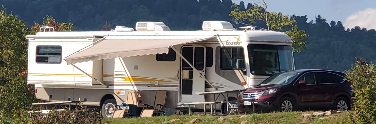
I recently upgraded from a 1992 35J to a 2004 39Z. The previous owner had replaced the gas/electric RV refrigerator with a residential unit. He explained that he kept it plugged in at his house, and then would only drive a few hours to a campground where he again plugged in. When it came time for new house batteries, he decided he only needed two batteries in lieu of the normal four. He also never ran the refrigerator off the inverter, although at some point the original converter/charger had been replaced with an Aimspower 2000 watt pure sine wave inverter.
Although I am not a hard core boondocker, I do have my times when I will spend up to a week or so away from the normal services. I also had concerns about cooling down the refrigerator before a trip. I didn’t have the option to keep power on the rig while in storage.
I knew the first order of business was going to be new house batteries. I also started thinking about something which I had absolutely zero experience with – solar power.
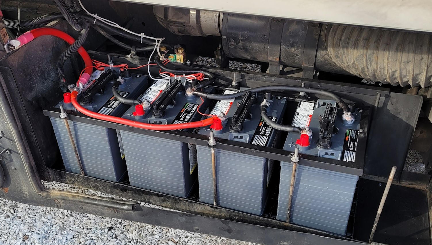
I installed four new 235 amp hour, six volt golf cart batteries. I would have preferred six batteries, but was lacking about 3/4” of space. Since the original battery trays, hold downs, and cables were all missing I had to make up a new battery hold down system. I started by installing sheet metal in the bottom of the battery compartment, then installed four new battery trays. A Group 24 battery tray works well to snugly hold the GCL golf cart battery. I threw away the fabric hold down straps and fabricated a new hold down clamp, utilizing the existing threaded rods. Everything I did building the battery hold downs and cabling was done with an eye towards easy access for watering batteries.
While I was installing the batteries, I also installed a Victron BMV-712 Battery Monitor. The shunt needs to be close to the batteries, and in order to mount securely, I installed a piece of 3/4” steel angle to the sheet metal partition behind the batteries. The angle also helped to stiffen the partition.

The next picture shows the hold down clamp fabricated from ¾” steel angle iron. I was able to reuse the tabs from the original hold down clamps. I had the heavy duty crimping tool so was able to fabricate my own cables.
With the custom hold down clamp, and careful routing of the battery cables, checking the water level is a snap.
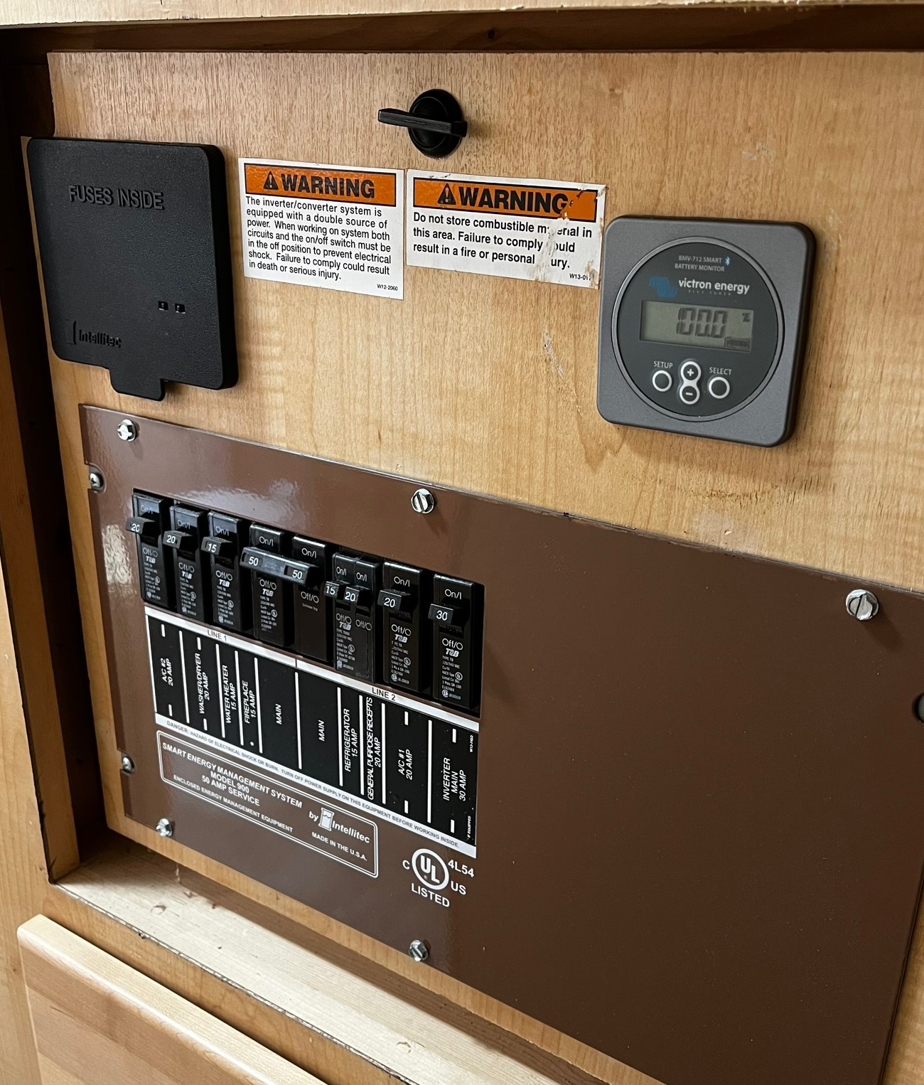
After mounting the shunt by the batteries, I elected to mount the BMV-712 monitor in the electrical closet by the bedroom. The BMV-712 has a smartphone bluetooth app which is much more convenient to use than the monitor, so I wasn’t concerned about having the monitor in an out of the way place. It also minimized the amount of wire fishing I had to do to connect the monitor to the shunt with the included RG-45 cable. I was able to drill/chisel a small hole at the bottom of the electrical closet, and another one at the bottom of the bed frame. Both holes ended up under the carpet and it was a fairly simple task to snake the wire under the carpet. (Harbor Freight sells a bundle of fibreglas rods that screw together for fishing wires – very handy!)
Red line shows where wires run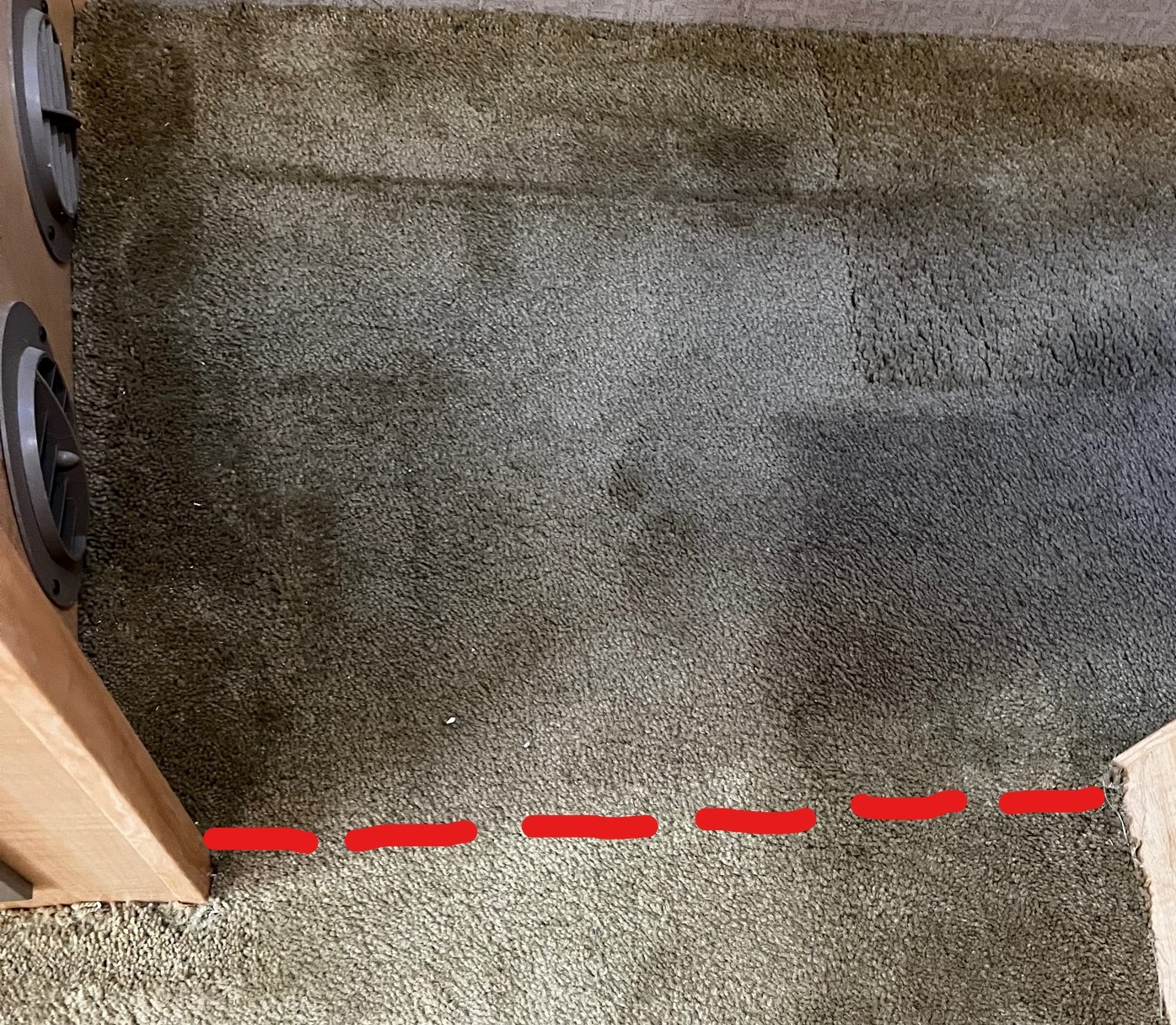
Now on to the solar part of the project! As I stated previously, I had zero knowledge of solar power, how much I needed, or how to install it. I joined and lurked on a number of Facebook groups dealing with solar power. I learned the first thing I had to do was figure out how much power I needed. I also found out its just about impossible to Google “how much solar power do I need to run a refrigerator” and get any kind of useful answer.
I started with my refrigerator which said it was rated at 140 watts.
140 watts/120 volts = 1.17 amps (AC)
1.17 amps X 12 volts = 14.0 amps (DC)
I knew the refrigerator wouldn’t be running continuously, so I took a guess at a 50% duty cycle, and came up with a DC amps requirement of 168 per day. I then noticed the Energy Star label on the refrigerator. It stated that it used 297 Kilowatt hours per year. Getting out my trusty calculator again:
297 Kwh per year/364 days = 815 watts per day
815 watts/120 volts = 6.79 amps per day (AC)
6.79 amps X 12 volts = 81.5 amps per day (DC)
I also used my Vectron Battery monitor to see how many amps were being used while the refrigerator ran, and also measured the refrigerator directly with a kilowatt meter. The kilowatt meter measured at about the number expected based on the Energy Star rating, and the battery monitor measured at the high end – about 170 amps per day. I did a very poor job of insuring everything else was off when I used the battery monitor to measure consumption. It appeared to me that the inverter was drawing quite a bit of power, but that will need to be an issue for another day.
I began to feel pretty comfortable planning for a consumption of about 150 amps per day. With 470 amp hours of battery capacity, I can use 235 amp hours before I reach a 50% state of charge (the level of discharge recommended for lead acid batteries). I’d be good for about a day and a half on batteries alone.
As I started to read about solar panels I learned that, A. You’ll rarely, if ever, get the rated power out of them, and B. The power output is determined by sun angle and time of exposure. There are charts and graphs available that will tell you the optimum angle to tilt your solar panels based on your latitude and time of year. I have enough to do when setting up camp, and wasn’t about to add climbing on the roof and adjusting solar panels to the list. My panels were going down flat. After reading a number of articles it seemed that about five hours a day is a good rule of thumb for how long you’ll get whatever your maximum solar output is.
With a need to produce about 150 amps per day, I began thinking I would need panels that could produce about 30 amps per hour. I had been looking at a couple of 200 watt panels that would fit nicely on the roof. My math said that under optimum conditions I could expect them to produce 33 amps per hour. I quickly added a third panel to give me a theoretical output of 50 amps per hour.
My next, and biggest, concern was how to mount the panels securely to the roof. I wasn’t philosophically opposed to drilling and sealing holes in the roof, but as soon as I looked into the composition of the roof I knew that would never work. I removed the interior portion of the skylight in the shower and found ……… nothing!
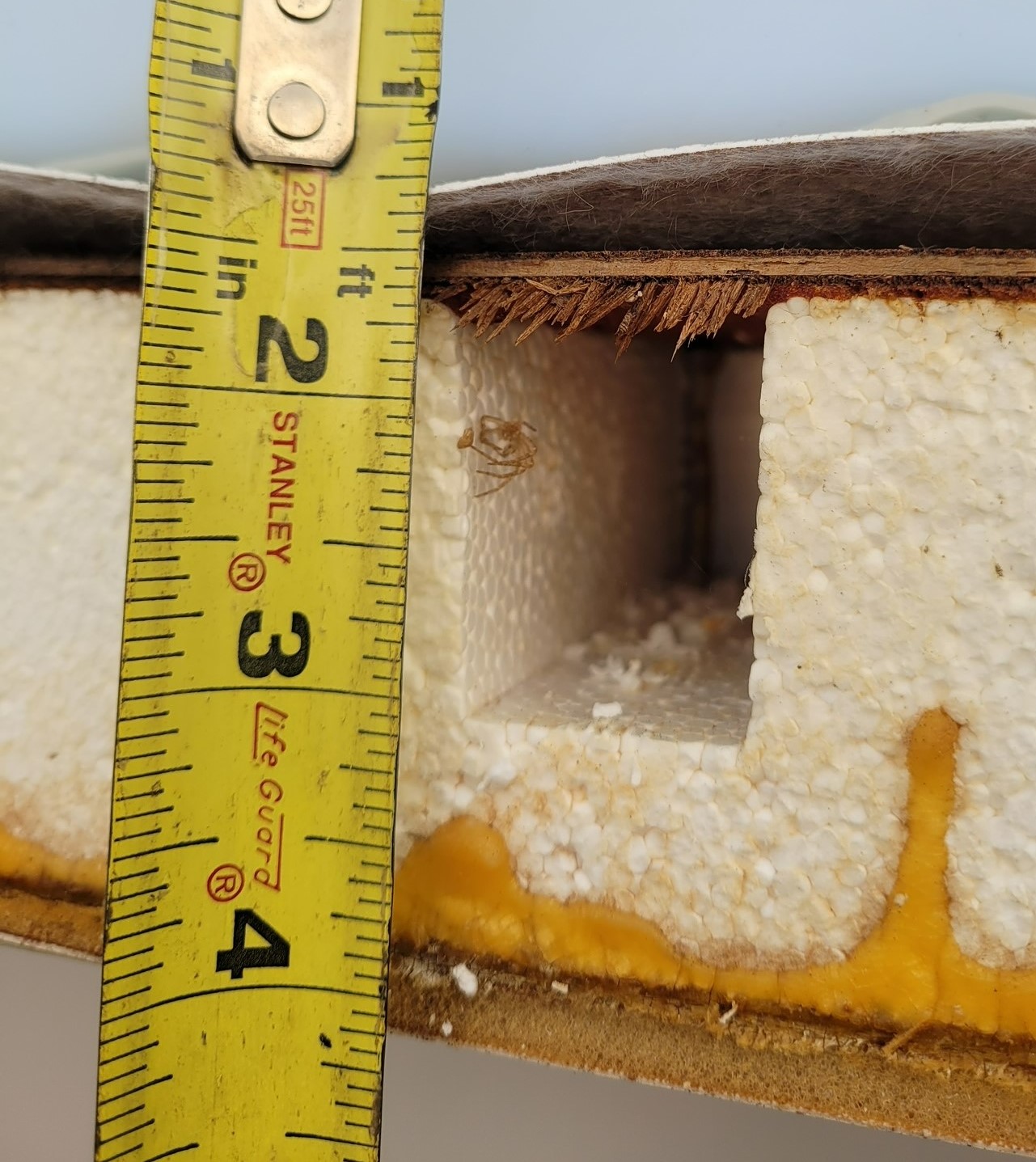
I knew I had a TPO roof, but was rather surprised on what it was mounted on. I had been on the roof previous to this and found it to be solid and secure, so I guess the styrofoam/thin wood veneer works for that purpose. Short of thru bolts and backing plates no way was I going to trust any type of fastener in that styrofoam. A number of people suggested VHB tape – and an equal number stated they would never use such a thing on a glued on membrane. I found myself in the former category. I found a very informative You-Tube video (and promptly lost the link – sorry) that showed a roof replacement on my type roof. It showed that there were several metal ribs spanning the roof. I tried finding them with a studfinder, and also looking on the roof early in the morning with the dew still on it. I didn’t feel I could adequately locate those ribs, and wasn’t sure that even then they would be strong enough or thick enough to support three panels (the panels I used weigh about 27 pounds each).
I began thinking in terms of some sort of roof rack device that I could securely attach to the side of the rig.
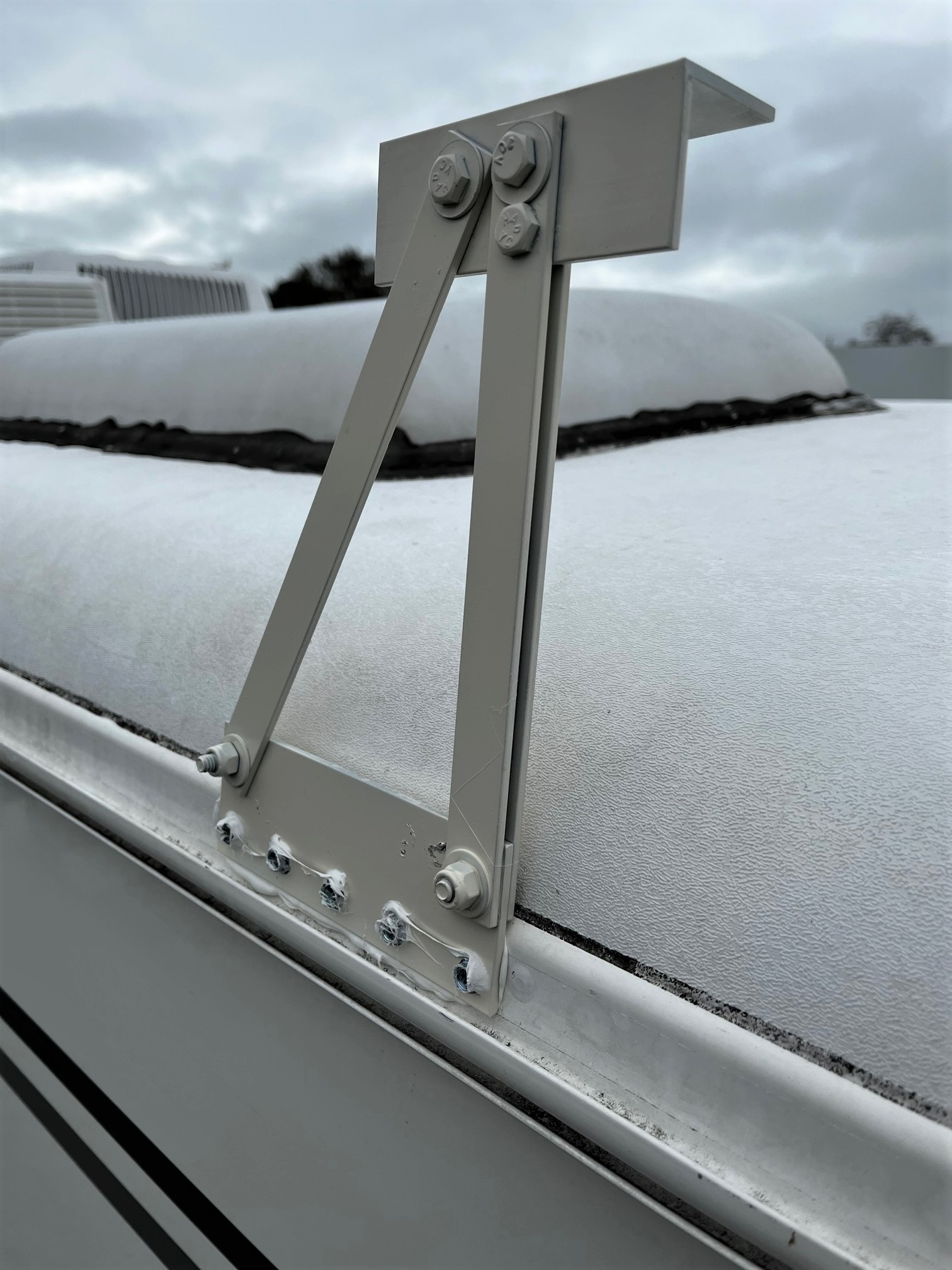
The rail attached to the side of the rig is 1/8 or 3/16 aluminum. It is riveted to the side of the rig every 6 inches and (I hope!) will be sturdy enough to support the solar panels. I started with 1/8” aluminum bar, 2” wide. I cut them 5 1/2” long, so they would fit flat between the rivets attaching the drip rail. The vertical pieces are 1/8” by 1” aluminum bar. I doubled up the verticals but only used a single for the diagonal brace. The top angle is 1/8”, 2 x 2 aluminum angle.
You cant see it in the picture, but there is a slight tilt to the 2 x 2 angle, to account for the 2” difference in height from front to rear.
I partially assembled the brackets before attaching them to the rig. You can’t get the bolts holding the vertical and diagonal bars in place once the 2” bar is attached to the rig. If you try to place the bolts pointing in, they will interfere with the roof membrane.
I used 5 #10 self tapping screws to attach the 2” bar to the rig, and then used 1/4-20 bolts with nylon lock nuts to attach the rest of the hardware.
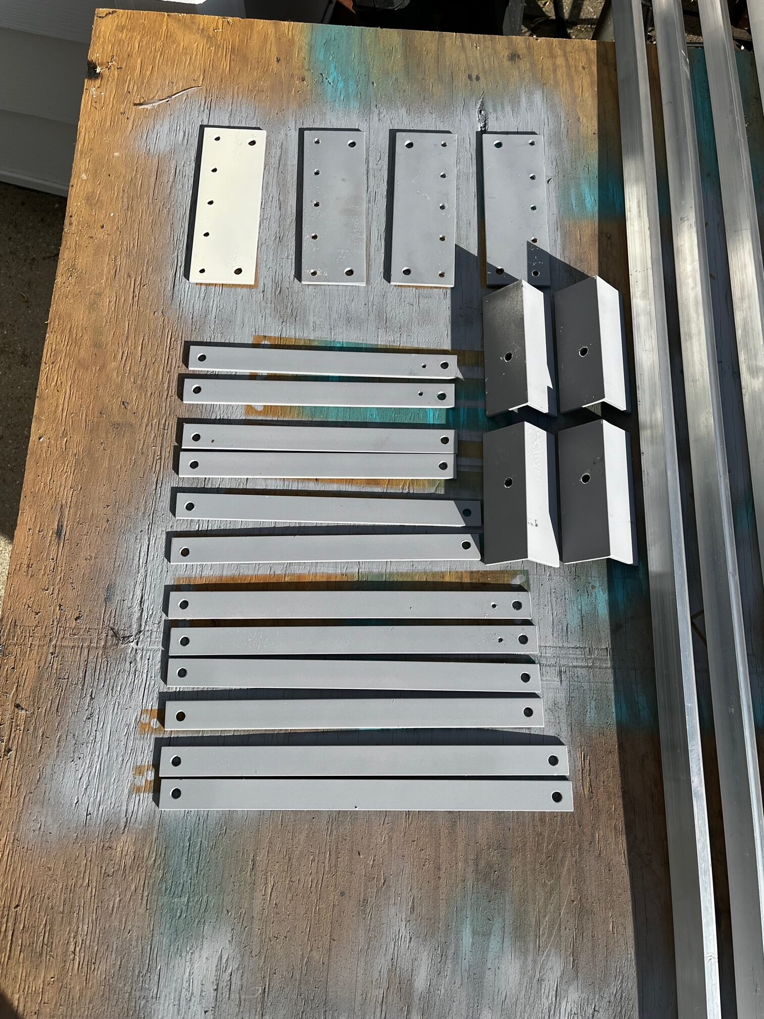
These are all the bracket pieces prior to assembly. Note length difference and that the 2 x 2 angle has only one hole drilled at this point. Once the partially assembled brackets were attached to the rig I placed an 8′ section of aluminum angle from the front to rear brackets to set the angle, then finished drilling holes to attach the 2 x 2 angle on top at the proper angle.
Once the four brackets were attached I installed the two cross pieces that the panels would ultimately mount to. I originally thought I could get by with a single 2 x 2 aluminum angle, but that proved to be much too unstable. I had to double them up. I made several mistakes at this point. I had been buying all my aluminum bars and angles at the local Home Depot and Lowes. They only had stuff with a max length of 8′, and I needed at least 8′ 3” to span the rig. The strength of the splice didn’t concern me, but I found out too late that the local metal supermarket had the lengths I needed, would cut it to length at no charge, and most importantly – their prices were about 20% lower than the box stores.
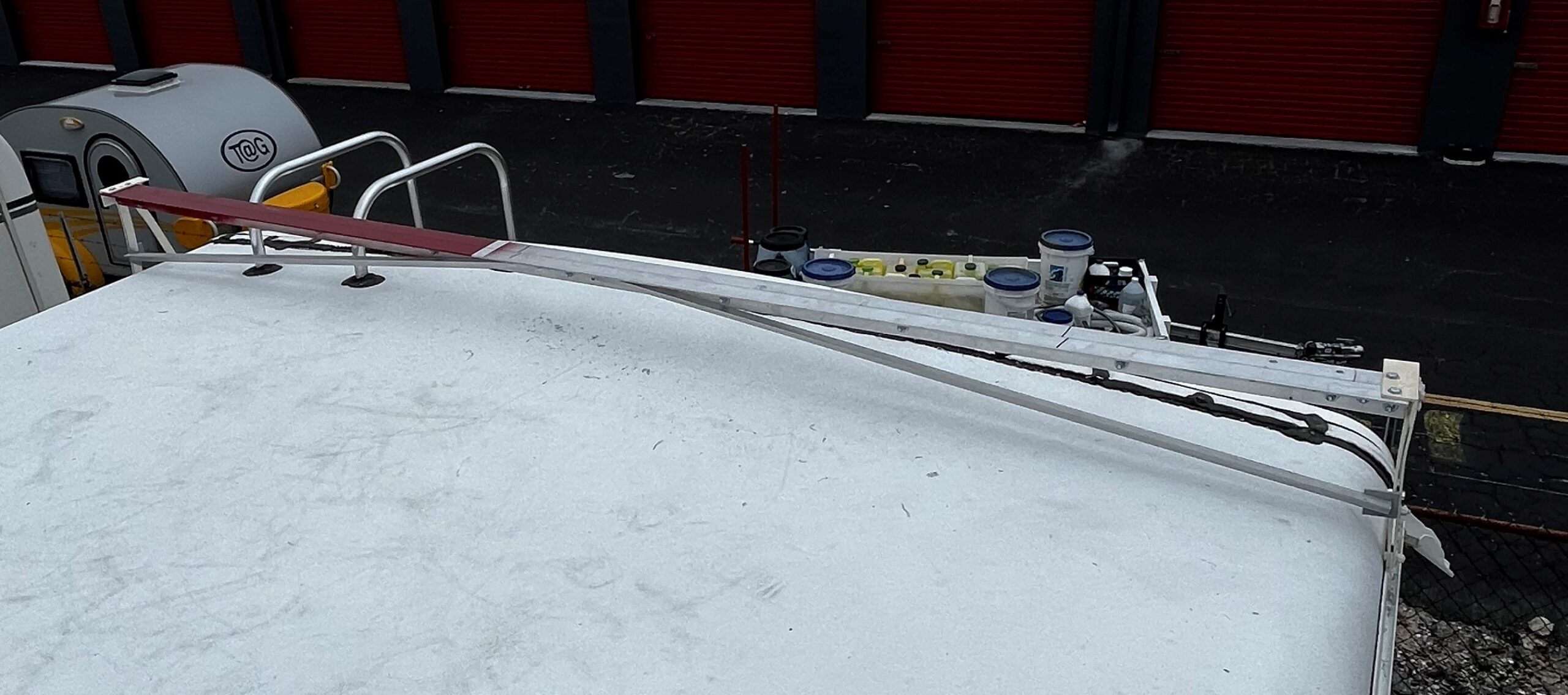
The final pieces were 1 x 1 aluminum angles installed for additional sideways support. Which leads me to another faux pas – I made my front bracket a little too short, so the diagonal brace was rubbing on the roof. After I thought I was done I had to add 1 1/2” spacers under the front cross rail for better clearance on the roof.
It was now (finally) time to mount the actual panels. I originally used three 1 x 1 aluminum angles, along with brackets of the same material, mounted to the solar panels, and then mounted to the “roof rack”. The aluminum turned out to be much too flexible for the job, so I had to replace them with 1 x 1 steel angles.
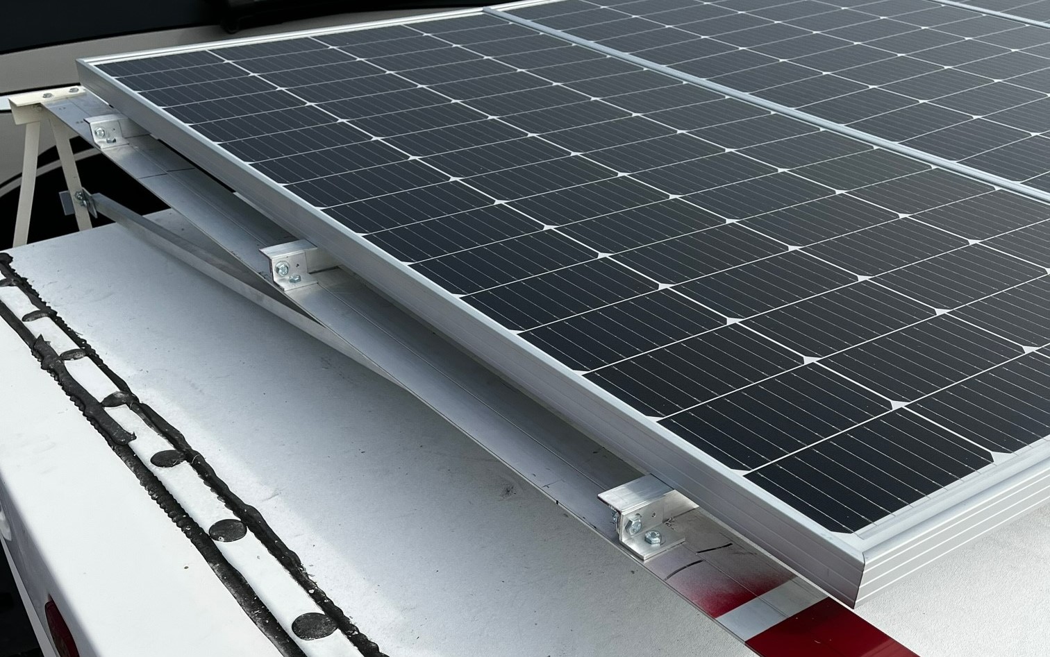
I was able to use the existing mounting holes on the solar panels to mount the steel angle. This lent itself well to the use of those small brackets to attach the solar panel angles to the roof cross braces. If I need to get the panels out of the way for cleaning or roof maintenance I can remove three bolts and raise the panels out of the way. It would also lend itself well towards some type of tilting mechanism if one was so inclined.
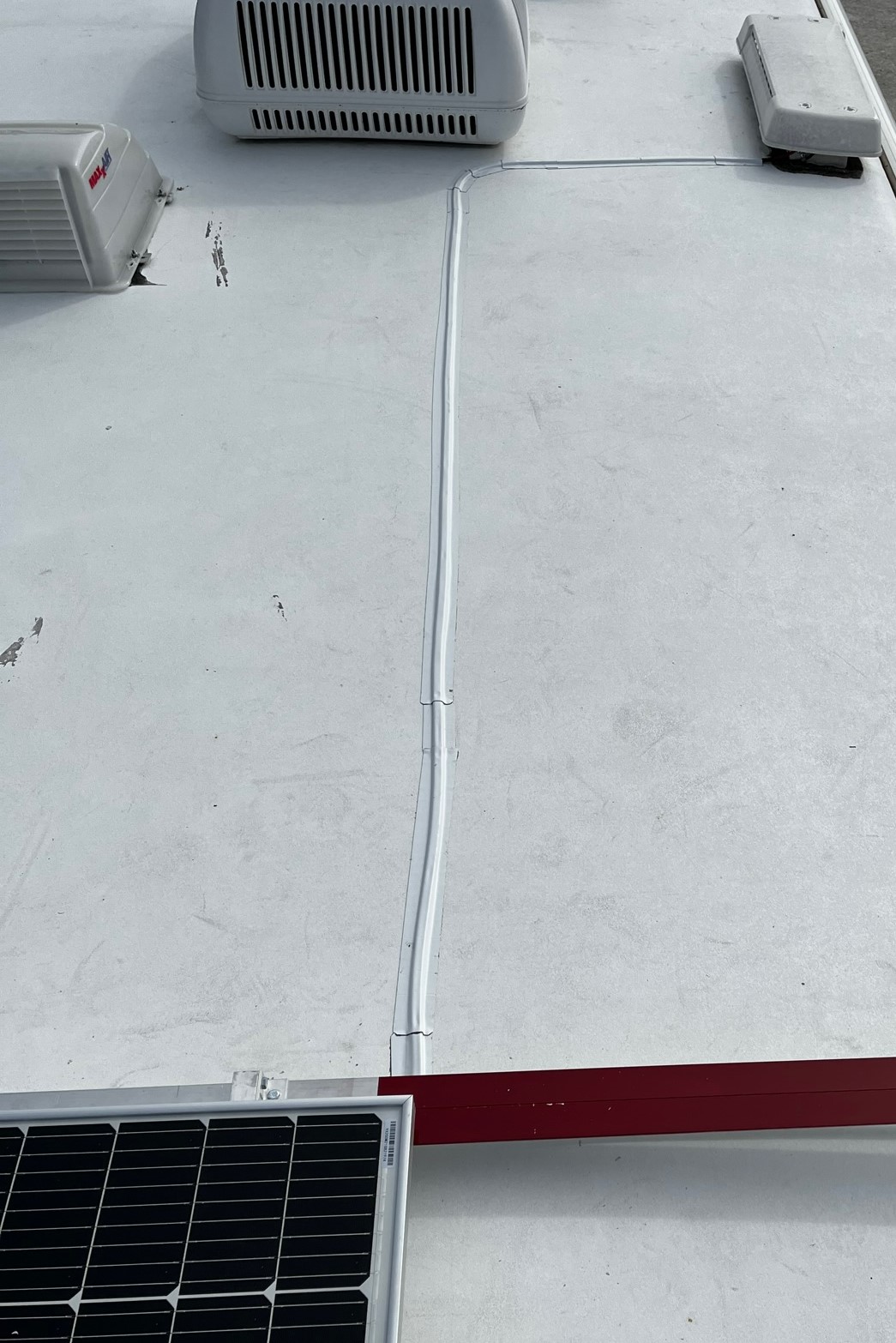
The final step on the roof was to route the wires from the panels into the rig. The wires were led forward to the existing refrigerator vent and down into the rig. I used two inch Eternabond to secure the wires to the roof.
Once the wires were inside the rig, my 39Z lent itself very well to running wires. I decided to locate the solar controller on the bedroom side of the electrical closet wall. There is an existing channel in the hall closet for wiring and I only needed to drill a couple holes in the refrigerator vent wall to get into that channel.
The area behind the electric panel has lots of room to work for running wires. Removing a couple drawers and the furnace vent gave me access from the ceiling to the floor. Just be sure to secure the wires to the back of that area so the drawers don’t interfere with them.
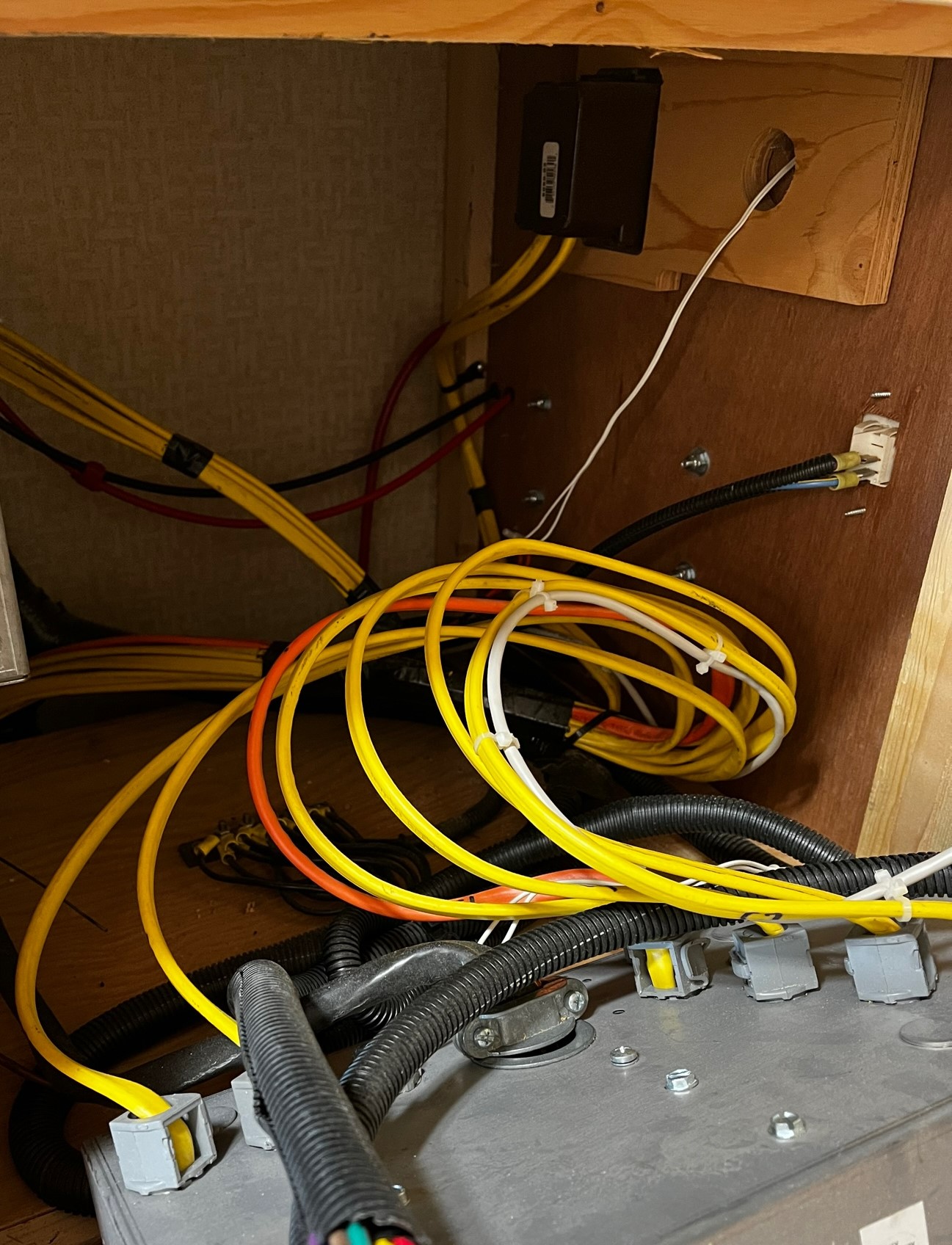
Electrically, I choose to wire the three solar panels in series. The higher voltage carries the same load with less amps, allowing me to use smaller wire to get to the controller. I had a total wire run of about 25′ and used 10 gauge wire for that. From the controller to the batteries, I had a total run of about 20′. Since the voltage going to the batteries is 12 volts, the amperage is correspondingly higher, so I used 6 gauge wire for that run. I was able to route the wires to the batteries using the same channel I’d used for the battery monitor cable. The wires go under the bed, then through a couple holes into the engine compartment and to the batteries.
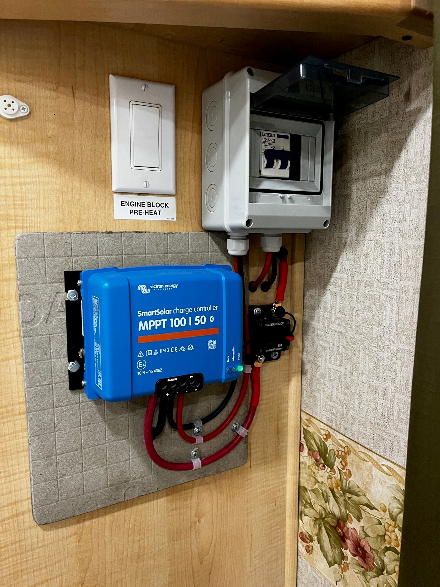
After installing the Victron battery monitor, I was impressed with the Victron quality and ease of use, so I opted for a Victron MPPT 100/50 SmartSolar controller. The SmartSolar has the bluetooth built in and makes adjusting and monitoring from your phone very simple. I also installed a Victron Smart Battery Sense which measures the battery voltage and temperature at the battery, and then networks with the other Victron components to more efficiently keep the batteries charged.
After installing the solar controller, I noticed that it did get a little warm, so I redid the installation using cement backerboard to protect the wood behind the controller. To finish the installation I installed a double pole switch/circuit breaker to disconnect the solar panels if necessary, and a circuit breaker in the positive lead to the battery.
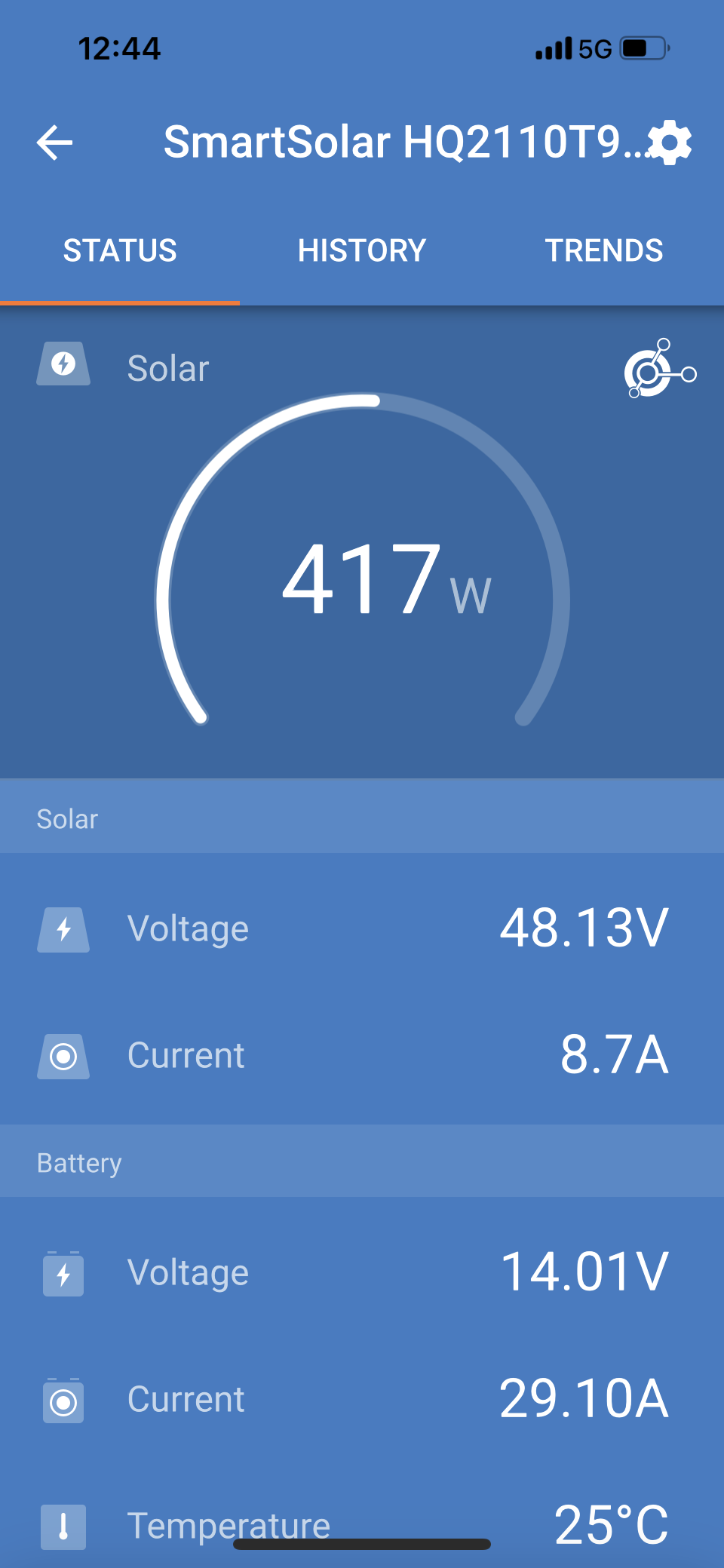
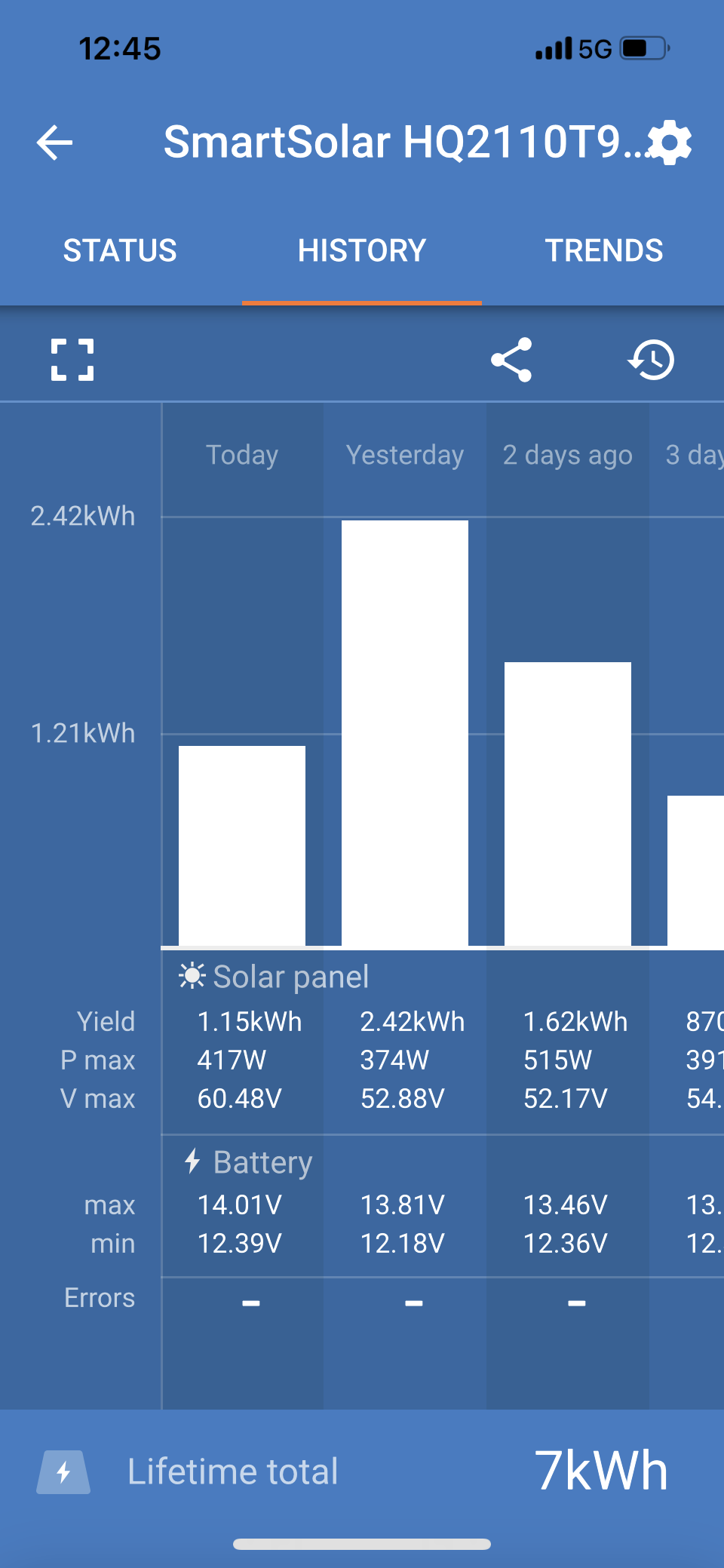
With the installation complete, I turned on the solar panels and refrigerator, and was able to keep the beer cold courtesy of Mother Nature. I had the rig in storage (in Florida – the sunshine state) for the next month and a half with no issues. While the power production (see below) seemed a little lower than I’d planned on, the battery state of charge was back up to 100% by noon, or early afternoon, each day. It was a bit unseasonably cool during that time, so that may have accounted for the refrigerator not having to work as hard.
As I had mentioned previously, I thought the inverter/charger was drawing quite a bit of power at idle. I’d had the rig washed and when I checked the rig after, the inverter was wet and inoperative. It came back to life after drying out a couple days – and seemed to be fine. But I remained wary of it. When I moved the rig to a site with full hookups, I started having troubles. The charger part of the inverter/charger wasn’t keeping up with the DC loads, and then the inverter started shutting down overnight.
The battery and solar installation, now became a battery, solar, and inverter/charger installation. I again opted for Victron equipment. It’s a bit pricey, but they seem to be constructed well, are easy to set up for my lead acid batteries, and play nicely together. I arranged to have a new Victron Multiplus 2000VA inverter/charger shipped to my next destination (my brother in law’s back yard where I knew additional tools awaited). A quick trip to Home Depot got me the steel I needed to make a couple brackets to mount the new unit vertically, then the installation was done in a couple hours.
I now seem to have a rig that I can boondock in when necessary, and other than the air conditioners, have all my electrical needs supplied by solar. I’ve found that I can even brew a pot of coffee in the morning. That will reduce the state of charge by about 4%, which is quickly replenished as the sun shines.
When everything was all said and done I had the following expenses for parts and materials:
Batteries, trays, and mounting $ 932
Solar panels, controller, cables 1393
Solar panel mounting 510
Inverter/charger and mount 1300
Since the installation, I’ve traveled about 2,000 miles on everything from back roads to interstates. So far, everything seems to be holding up well.